
Schneider LTMR08EBD Motor controller LTMR TeSys T - 24 V DC 8 A for Ethernet TCP/IP New & Original with very competitive price and One year Warranty
New & Original
LTMR08EBD
Please contact us for more information.
- Product description
- Contact us
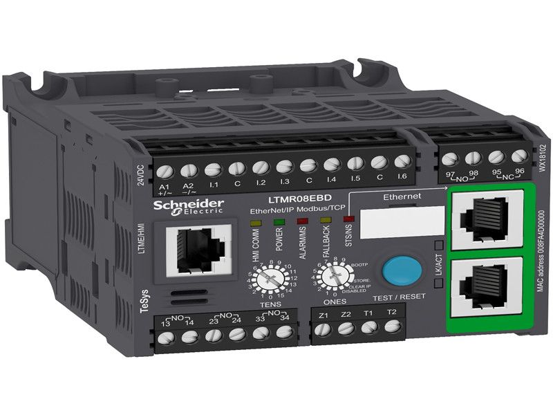
Schneider LTMR08EBD Motor controller LTMR TeSys T - 24 V DC 8 A for Ethernet TCP/IP
New & Original with very competitive price and One year Warranty
TeSys T is a smart motor management system. When associated with a short circuit protection device and a contactor,
the device provides full motor monitoring, control and protection for electrical motors.
| range | TeSys | |
|---|---|---|
| product name | TeSys T | |
| device short name | LTMR | |
| product or component type | Motor controller | |
| device application | Equipment monitoring and control | |
| measurement current | 0.4…8 A | |
| [Us] rated supply voltage | 24 V DC | |
| current consumption | 56...127 mA | |
| supply voltage limits | 20.4…26.24 V DC | |
| communication port protocol | Modbus TCP/EtherNet/IP | |
| bus type | Ethernet IEEE 802.3 interface, addressing 0...159, transmission rate 10...100 Mbit/s, RJ45 with 2 shielded twisted pairs |
| [Ui] rated insulation voltage | 690 V conforming to EN/IEC 60947-1 690 V conforming to CSA C22.2 No 14 690 V conforming to UL 508 | |
|---|---|---|
| [Uimp] rated impulse withstand voltage | 6 kV current or voltage measurement circuit conforming to EN/IEC 60947-4-1 0.8 kV communication circuit conforming to EN/IEC 60947-4-1 0.8 kV supply, inputs and outputs conforming to EN/IEC 60947-4-1 | |
| short-circuit withstand | 100 kA conforming to EN/IEC 60947-4-1 | |
| associated fuse rating | 4 A gG for output 0.5 A gG for control circuit | |
| protection type | Phase failure Locked rotor Earth-leakage protection Thermal protection Overload Phase unbalance Reverse polarity protection Power factor variation Overload (long time) Thermal overload protection Load fluctuation | |
| network and machine diagnosis type | Event recording Remaining operating time before overload tripping Trip context information Waiting time after overload tripping Running hours counter/operating time Trip history information Fault recording Starting current and time Phase fault and earth fault trip counters Motor control command recording | |
| logic input number | 6 | |
| input current | 7 mA | |
| current state 0 guaranteed | Logic input: < 5 V and <= 15 mA for 5 ms | |
| current state 1 guaranteed | Logic input: < 15 V and 2...15 mA for 15 ms | |
| maximum output switching frequency | 2 Hz | |
| load current | 5 A at 250 V AC for logic output 5 A at 30 V DC for logic output | |
| permissible power | 480 VA (AC-15), Ie = 2 A, 500000 cycles (output) 30 W (DC-13), Ie = 1.25 A, 500000 cycles (output) | |
| maximum operating rate | 1800 cyc/h | |
| contacts type and composition | 1 NO + 1 NC fault signal 3 NO | |
| metering type | Average current Iavg Temperature Earth-fault current Phase current I1, I2, I3 RMS Imbalance current | |
| measurement accuracy | 5...15 % earth fault current internal measurement (for current > 0.1 A) 1 % voltage (100...830 V) 3 % power factor (cos φ > 0.6) 5 % earth fault current external measurement (< 5 % or 0.01 A) +/- 30 min/year internal clock 0,02 temperature 1 % current 5 % active and reactive power | |
| overvoltage category | III | |
| connection pitch | 5.08 mm |

Related Products
-

Ready To Ship Original Schneider Variable speed drive ATV630D45N4
LTMR08EBD Read more -
In Stock New & Original SCHNEIDER XCSE73117 Safety switch
LTMR08EBD Read more -

In Stock New & Original SCHNEIDER ABE7R16T210 Sub-base with plug-in electromechanical relay ABE7 - 16 channels - relay 10 mm
LTMR08EBD Read more -

Brand New SCHNEIDER analog isolated high level output module BMEAHO0412 Original In Stock
LTMR08EBD Read more