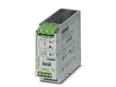
Phoenix Redundancy module, with protective coating - QUINT-ORING/24DC/2X20/1X40 - 2320186
Active QUINT redundancy module for DIN rail mounting with ACB (Auto Current Balancing) Technology and monitoring functions,
input: 24 V DC/2x 20 A, output: 24 V DC/1 x 40 A, including mounted UTA 107/30 universal DIN rail adapter.
Key Commercial Data
| Orderkey | 2320186 |
|---|
| Packing unit | 1 pc |
|---|
| Catalog page | Page 303 (C-4-2019) |
|---|
| GTIN | 4046356524919 |
|---|
| Weight per Piece (excluding packing) | 752.800 g |
|---|
| Custom tariff number | 85049091 |
|---|
| Country of origin | CN (China) |
|---|
Dimensions
| Width | 38 mm |
|---|
| Height | 130 mm |
|---|
| Depth | 125 mm |
|---|
| Width with alternative assembly | 122 mm |
|---|
| Height with alternative assembly | 130 mm |
|---|
| Depth with alternative assembly | 41 mm |
|---|
Ambient conditions
| Degree of protection | IP20 |
|---|
| Ambient temperature (operation) | -25 °C ... 70 °C (> 60 °C Derating: 2.5 %/K) |
|---|
| Ambient temperature (storage/transport) | -40 °C ... 85 °C |
|---|
| Max. permissible relative humidity (operation) | ≤ 100 % (at 25 °C, non-condensing) |
|---|
| Climatic class | 3K3 (in acc. with EN 60721) |
|---|
| Degree of pollution | 2 |
|---|
| Installation height | 2000 m |
|---|
Input data
| Nominal input voltage range | 24 V DC |
|---|
| Input voltage range | 18 V DC ... 28 V DC (SELV) |
|---|
| Nominal input current | 2x 20 A (-25 °C ... 60 °C) |
|---|
| 1x 40 A (-25 °C ... 60 °C) |
|---|
| Maximum input current | 2x 26 A (-25°C ... 40°C) |
|---|
| 1x 52 A (-25°C ... 40°C) |
|---|
| 120 A (12 ms, SFB Technology) |
|---|
Output data
| Nominal output voltage | 0.2 V (< DC input) |
|---|
| Nominal output current (IN) | 40 A (Increasing power) |
|---|
| 20 A (Redundancy) |
|---|
| Derating | 60 °C ... 70 °C (2.5%/K) |
|---|
| Connection in series | No |
|---|
| Protection against overvoltage at the output (OVP) | ≤ 32 V DC |
|---|
| Power loss nominal load max. | 8 W (IOUT = 40 A) |
|---|
General
| Net weight | 0.6 kg |
|---|
| Efficiency | > 98 % |
|---|
| Protection class | III |
|---|
| Degree of protection | IP20 |
|---|
| MTBF (IEC 61709, SN 29500) |
|
|---|
| > 720000 h (40 °C) |
|---|
|
|
|---|
| Mounting position | horizontal DIN rail NS 35, EN 60715 |
|---|
| Assembly instructions | alignable: PN ≥50%, 5 mm horizontally, 15 mm next to active components, 50 mm vertically
alignable: PN <50%, 0 mm horizontally, 40 mm vertically top, 20 mm vertically bottom |
|---|
Connection data, input
| Connection method | Screw connection |
|---|
| Conductor cross section solid min. | 0.2 mm² |
|---|
| Conductor cross section solid max. | 6 mm² |
|---|
| Conductor cross section flexible min. | 0.2 mm² |
|---|
| Conductor cross section flexible max. | 4 mm² |
|---|
| Conductor cross section AWG min. | 10 |
|---|
| Stripping length | 8 mm |
|---|
| Screw thread | M3 |
|---|
Connection data, output
| Connection method | Screw connection |
|---|
| Conductor cross section solid min. | 0.5 mm² |
|---|
| Conductor cross section solid max. | 16 mm² |
|---|
| Conductor cross section flexible min. | 0.5 mm² |
|---|
| Conductor cross section flexible max. | 16 mm² |
|---|
| Conductor cross section AWG min. | 6 |
|---|
| Stripping length | 10 mm |
|---|
| Screw thread | M4 |
|---|
Connection data for signaling
| Connection method | Screw connection |
|---|
| Conductor cross section solid min. | 0.2 mm² |
|---|
| Conductor cross section solid max. | 6 mm² |
|---|
| Conductor cross section flexible min. | 0.2 mm² |
|---|
| Conductor cross section flexible max. | 4 mm² |
|---|
| Conductor cross section AWG min. | 16 |
|---|
| Conductor cross section AWG max. | 10 |
|---|
| Stripping length | 10 mm |
|---|
| Screw thread | M3 |
|---|
Standards
| Standard - Electrical safety | EN 60950-1/VDE 0805 (SELV) |
|---|
| Standard – Electronic equipment for use in electrical power installations and their assembly into electrical power installations | EN 50178/VDE 0160 (PELV) |
|---|
| Standard – Safety extra-low voltage | IEC 60950-1 (SELV) and EN 60204-1 (PELV) |
|---|
Conformance/approvals
| UL approvals | UL/C-UL listed UL 508 |
|---|
| UL/C-UL Recognized UL 60950-1 |
|---|
| UL ANSI/ISA-12.12.01 Class I, Division 2, Groups A, B, C, D (Hazardous Location) |
|---|
EMC data
| Electromagnetic compatibility | Conformance with EMC Directive 2014/30/EU |
|---|
| Low Voltage Directive | Conformance with LV directive 2006/95/EC |
|---|
| Electrostatic discharge | EN 61000-4-2 |
|---|
| Contact discharge | 8 kV (Test Level 4) |
|---|
| Discharge in air | 15 kV (Test Level 4) |
|---|
| Electromagnetic HF field | EN 61000-4-3 |
|---|
| Frequency range | 80 MHz ... 1 GHz |
|---|
| Test field strength | 20 V/m (Test Level 3) |
|---|
| Frequency range | 1 GHz ... 2 GHz |
|---|
| Test field strength | 10 V/m (Test Level 3) |
|---|
| Frequency range | 2 GHz ... 3 GHz |
|---|
| Test field strength | 10 V/m (Test Level 3) |
|---|
| Comments | Criterion A |
|---|
| Fast transients (burst) | EN 61000-4-4 |
|---|
| Input | 2 kV (Test Level 3 - asymmetrical) |
|---|
| Output | 2 kV (Test Level 3 - asymmetrical) |
|---|
| Signal | 2 kV (Test Level 4 - asymmetrical) |
|---|
| Comments | Criterion B |
|---|
| Surge voltage load (surge) | EN 61000-4-5 |
|---|
| Input | 1 kV (Test Level 2 - symmetrical) |
|---|
| 2 kV (Test Level 3 - asymmetrical) |
|---|
| Output | 1 kV (Test Level 2 - symmetrical) |
|---|
| 2 kV (Test Level 3 - asymmetrical) |
|---|
| Signal | 1 kV (Test Level 2 - asymmetrical) |
|---|
| Comments | Criterion B |
|---|
| I/O/S | asymmetrical |
|---|
| Frequency range | 0.15 MHz ... 80 MHz |
|---|
| Voltage | 10 V (Test Level 3) |
|---|
| Comments | Criterion A |
|---|
| Criterion A | Normal operating behavior within the specified limits. |
|---|
| Criterion B | Temporary impairment to operational behavior that is corrected by the device itself. |
|---|